


HHL MOBIUS
SUMMARY:
Mobius is a modular, adaptable rail system to be used in place of decorative architectural molding throughout the home and serves as an anchor for a variety of grab bar and accessibility attachments. Mobius can be used in various configurations throughout the home—including the bedroom, bathroom, hallways, stairways, and living room. The attachments can be easily installed, removed, and repositioned anywhere along the structural rail without the need of costly and timely home modifications or professional installation. The system is highly reconfigurable to changing user needs and abilities over time. It is easy to install as well as having the ability to blend into the bathroom, addressing the issues of aesthetics for adaptive equipment. I contributed to Mobius mostly by creating illustrations and renderings of the system for product visualization, but I also supported product testing and FEA analysis on different rail designs.
TIMELINE:
-
I have been involved in this project in a supporting role from May 2022 to September 2024. My involvement in Mobius again began in January 2026. Project is on going but my involvement was shifted to other projects like ShowerSteady.
PROJECT LEAD:
PROJECT TEAM:
SKILLS LEARNED/UTILIZED: Brainstorming and ideation sessions; illustration, project visualization and rendering using Procreate; testing rig creation and testing conduction; FEA and mechanical stress analyses
MY CONTRIBUTIONS TO DEVELOPMENT
Ideation, Illustration, and Concept Rendering
May 2022 - January 2024
For background on the innovation, Mobius is an adaptive rail system visually appearing as decorative architectural molding. It is used to mount various types of grab bars or assistive technology attachments for navigating throughout the home, especially in places with increased fall risk like the bathroom. Its modular design affords the system to adapt to a user's changing needs over time. Its aesthetic design affords the ability to blend into the background and avoid a person's home from "looking like a hospital" which was a common problem with older adult stakeholders our team interviewed. After the Mobius base rail was screwed to the wall and and concealed with all covers, the Mobius system is installed via the following steps:
-
Remove the inner architectural snap-on molding
-
Attach the component to the structural rail t-channel
-
Conceal the component attachment plates with molding cover pieces
-
Cut the inner architectural moulding as needed to cover the structural rail
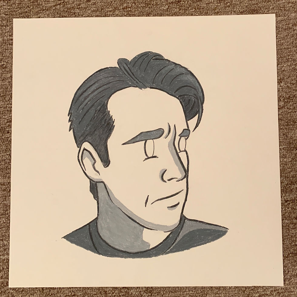
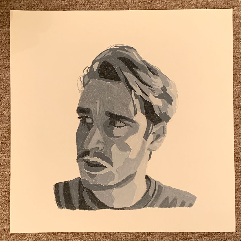
When I began my involvement with the HHL in May 2022, my first task was creating illustrations of the Mobius system, highlighting how it is assembled and installed. The purpose of these illustrations were for the following reasons:
-
Visualize how the system works and is assembled (Image 1 and 2) These were used in marketing briefs, promotional material like flyers and posters, and for grant submissions.
-
Explain the system in an easy to understand way during focus group sessions for end users
-
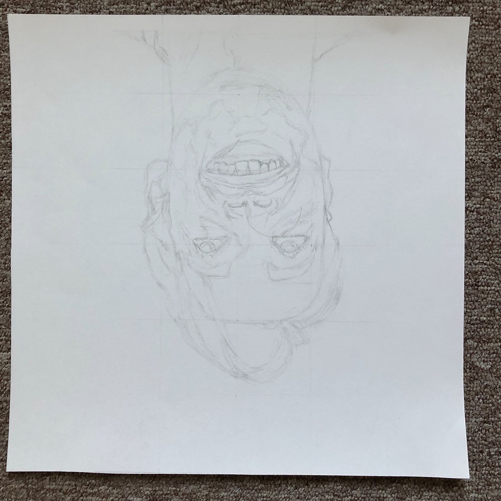
Documentation of the design evolution of the Mobius prototypes (Image 3)


As shown in the above illustrations, the system is comprised of 3 main component categories.
-
Aluminum base rail screwed to the wall
-
Decorative rail covers (edge covers, end caps, and middle cover sections)
-
Grab bar attachments installed via bolts and t-nuts
In addition to static illustrations, I also created an animation of a grab bar installation on the Mobius System. This video was used frequently in marketing presentations and for communicating the installation of the Mobius system in isolation.
Lastly, I created a series of 5 illustrations visualizing various ways the Mobius system could be used with different attachments in different parts of the house. In the bathroom, multilevel grab bars are used for transitioning from sitting to standing on/off the toilet. For bedrooms, fold up/down grab bars can be used for assistance with getting in and out of bed. For hallways and stairwells, the Mobius system can have multiple types of handrails or stair assist devices attached to it along its length. For the living room, exercise attachments can be installed, like hooks for exercise bands to he used on.


In addition to illustration, I also contributed to ideation of the Mobius System attachments. With the HHL team, I participated in various brainstorming sessions for Mobius, generating a variety of sketches for attachment tools and furniture designs. The furniture is not currently protected under IP protection, so they cannot be shown as of January 2026.
Prototype Testing & Mechanical Analysis
January 2024 - September 2024

Rig was made out of steel L brackets cut and welded together.

I used a chop saw to cut steel bracket segments that needed to be welded together.

I learned a little bit go MIG welding working on this with Project Lead, Paulina.
Rig was made out of steel L brackets cut and welded together.
Rig Fabrication and Strength Testing
In accordance with ISO 17966:2016, Mobius attachments are to comply with standardized testing of grab bars. I supported several static strength tests on Mobius. This included helping assemble a testing rig out of steel, which involved drilling, cutting, and some welding during assembly, this can be shown in the image on the left. The image of the test itself cannot be shown due to IP disclosure. In Image 1, the vertical portion of the rig on the right side of the image is mounted against the wall. The extension on the left side of the rig would hold a winch that would pull down on fold down Mobius grab bar attachments.
FEA & Mechanical Analyses
In addition to physical load testing, I conducted two rounds finite element analyses (FEAs) using SolidWorks Simulation Add-on. The first analysis is shown in images on the right. The goal of the first analysis was focused on testing different hollow profiles of the Mobius rail to determine how much of a profile cavity could be created for material/weight savings while maintaining appropriate strength. I tested two different profiles under simulated loading conditions and helped guide the decision of this hollow profile shape.
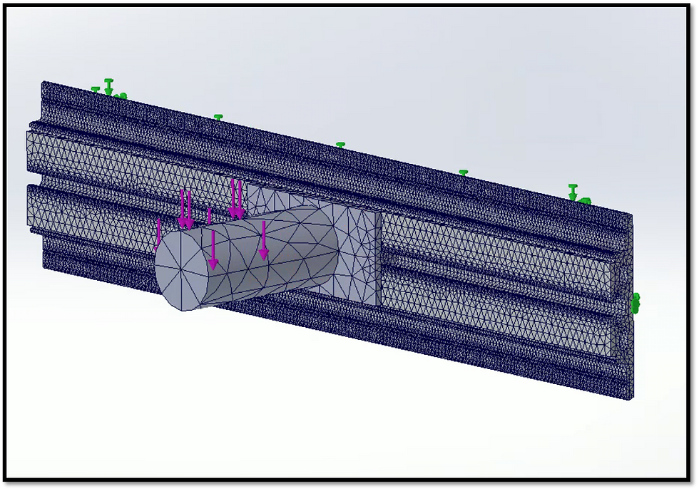
This is a SolidWorks mesh of the Mobius rail in a standard simulated loading condition. I am analyzing different profile cavities to optimize material usage to strength.

This is a resultant SolidWorks simulation of a Mobius rail in a standard simulated loading condition. I am analyzing different profile cavities to optimize material usage to strength.
This is a SolidWorks mesh of the Mobius rail in a standard simulated loading condition. I am analyzing different profile cavities to optimize material usage to strength.
The second round of FEA analyses (not shown) was testing three different Mobius mounting bracket profiles of vertical resistance band track. This track extended along the wall 3' above and below Mobius, so lever arms for mounts at the most distal ends of the track would generate large moments. FEA was necessary to determine optimal profile prior to fabrication.
The last analysis was on a fold down bedside grab bar. The team wanted a parameter study on strength and Factor of Safety (FoS) with a variety of permutations of different grab bar materials, tubing diameters, and thicknesses. As this is a simplified beam equation, I created a MATLAB code to compute the stress and FoS in each of the bar permutations. The images below show the results of the study. Image 1 is a chart of max load to cause before deflection (yield load). Image 2 is a spreadsheet of the outputted MATLAB matrix of stress values along the length of the grab bar. The coloring is due to conditional formatting of Factor of safety (red is yield or FoS<1, orange 1<Fos<1.5, yellow is 1.5<FoS<3, Green is FoS>3) to visually see where high stress is generated to communicate this to the team. This was deemed to be a faster approach than simulation due to limitations of accessing SolidWorks Simulation at the time of the analysis.


The coloring is due to conditional formatting of Factor of safety (red is yield or FoS<1, orange 1<FoS<1.5, yellow is 1.5<FoS<3, Green is FoS>3) to visually see where high stress is generated to communicate this to the team.

Zoomed in to see Parameters of the calculation